Example MaxPro-1: Constructing a MaxPro design for a 4-D input space
For this first MaxPro example, the goal is to construct a simple MaxPro design of size 10.
1. From the FOQUS main screen, click the SDoE button. On the top left side, select Load Existing Set, and select the cand_data_maxpro.csv file from examples folder. This identifies the possible input combinations from which the design will be constructed. The more possible candidates that can be provided to the search algorithm used to construct the design, the better the design might be for the specified criterion.
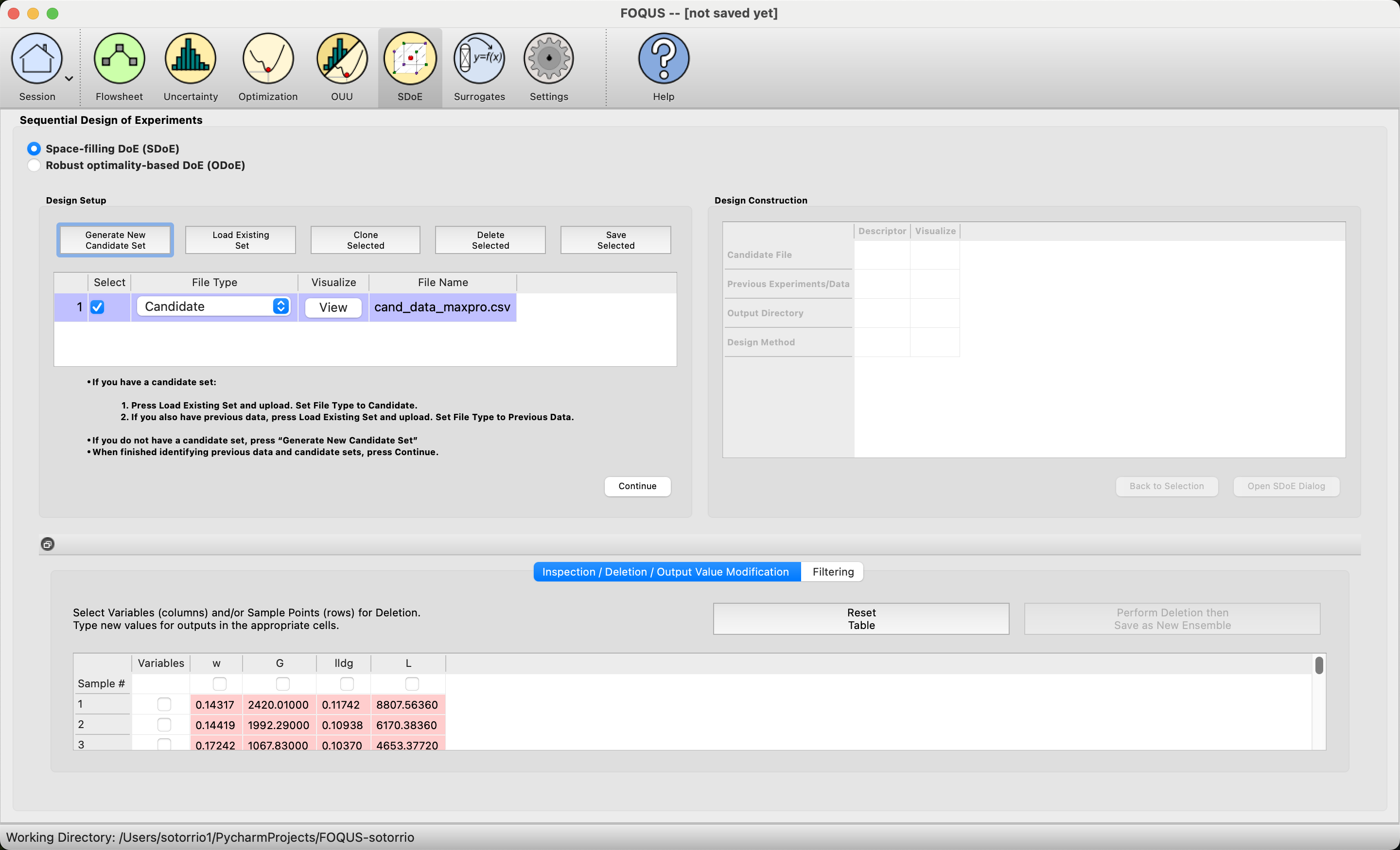
MaxPro Example 1: Load Candidate Set
2. Next, click on Continue to advance to the Design Construction Window, and then select Uniform Space Filling and click on Open SDoE Dialog to advance to the second SDOE screen, where particular choices about the design can be made. On the second screen, select MaxPro for the Optimality Method Selection. Change the Design Size to 10. There should be an _id column automatically created containing unique identifiers to identify which runs from the candidate set were chosen for the final designs. Since the ranges of each of the inputs are the bounds that we want to use for creating this design, we do not need to change the entries in Min and Max.

MaxPro Example 1: Design Setup
3. Once the choices for the design have been specified, click on the Estimate Runtime button to estimate the time taken for creating the design. For the computer on which this example was developed, it is estimated that the code would take 6 seconds to create the specified design. The higher the design size, the longer it will take to create the design. Once the design size has been decided, click Run SDOE.
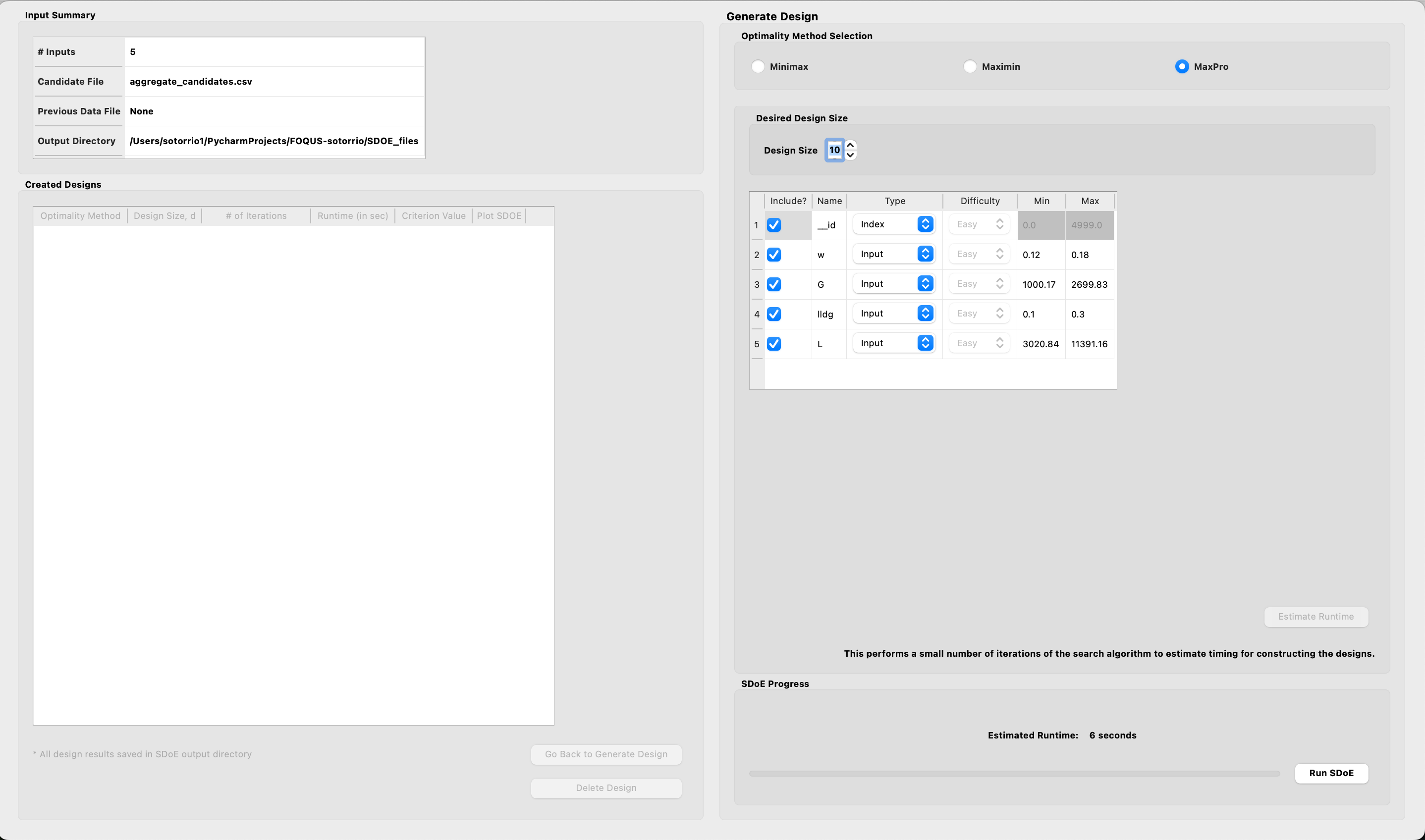
MaxPro Example 1: Time Estimate
After waiting for the prescribed time, the Created Designs window will have 1 MaxPro created design.
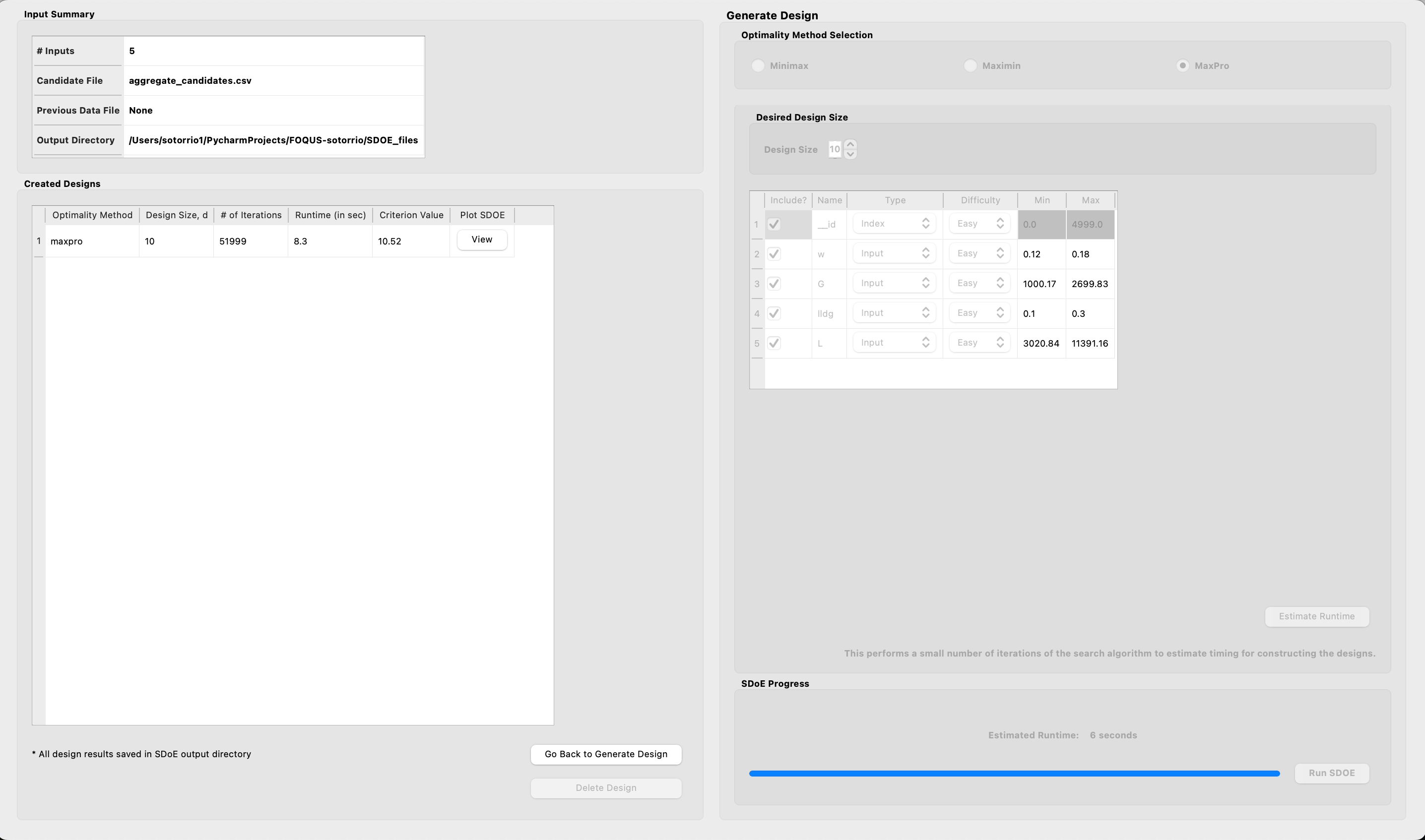
MaxPro Example 1: Created Design
5. By clicking on the View button under the Plot SDOE column in the Created Designs table, the user can select what inputs to graph.
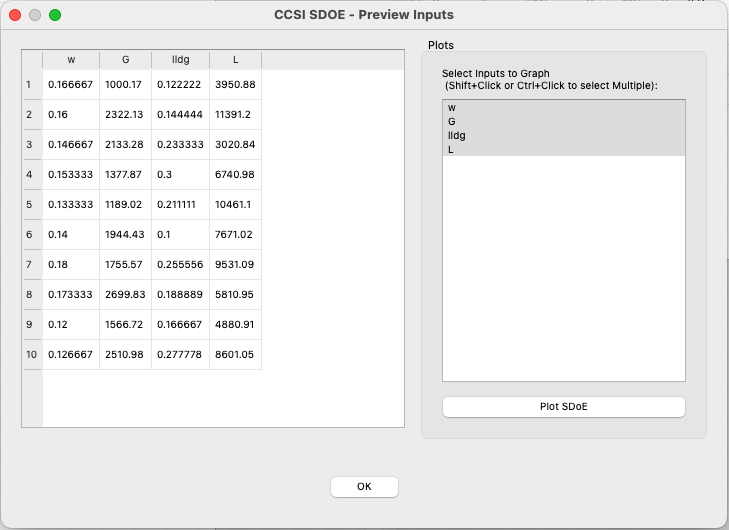
MaxPro Example 1: Preview Design
Once the inputs have been selected, click on the Plot SDoE button to visualize your design.
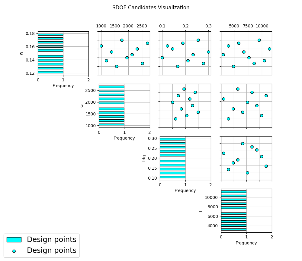
MaxPro Example 1: Plot Design
Example MaxPro-2: Constructing a MaxPro augmented design using the previously created design in example 1
In this example, we consider the sequential aspect of design, by building on the first example results. This is an adaptive design, which maximizes the MaxPro objective function.
1. In the Design Setup box, click on Load Existing Set to select the candidate set that you would like to use for the construction of the design. This may be the same candidate set that was used in Example 1, or it might have been updated based on what was learned from the first data collection. For example, if it was learned that one corner of the design space might not be desirable, then the candidate set can be updated to remove candidate points that are now considered undesirable. For the File Type leave the designation as Candidate.
To load in the experimental runs that were already collected, click on Load Existing Set again, and select the prev_data_maxpro.csv file from examples folder. This time, change the File Type to Previous Data. If you wish to view either of the candidate or previous data files, click on View to see either a table or plot.
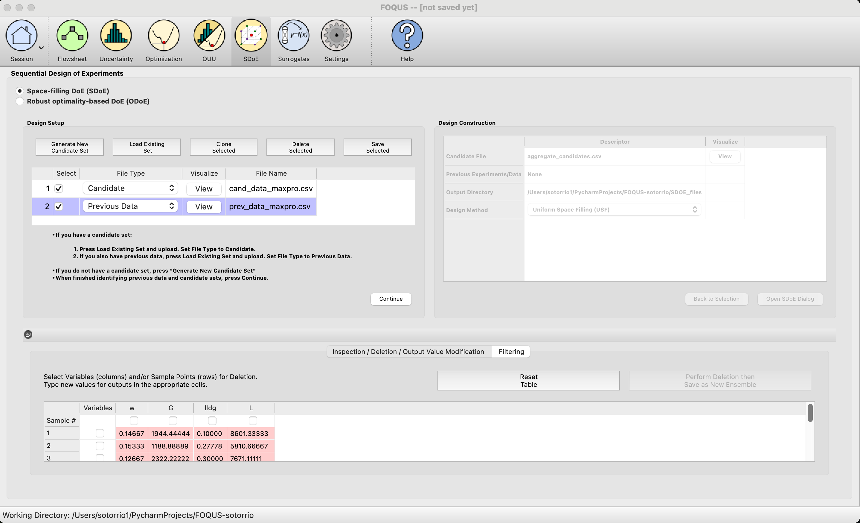
MaxPro Example 2: Load Data
2. Click on the Continue button at the bottom right of the Design Setup box. This will activate the Design Construction box. By clicking on the View button under the Visualize column, the user can see both the candidate set and the previous data set in the same plot.
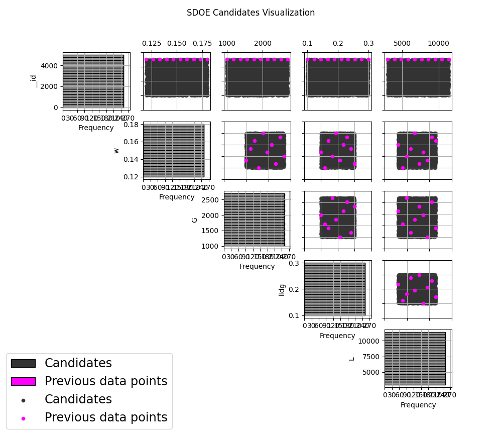
MaxPro Example 2: Plot Data
3. After examining that the desired files have been selected, click on the Uniform Space Filling button at the bottom right corner of the Design Construction window. This will open the second SDoE window that shows the Sequential Design of Experiments Set-Up window on the right hand side.
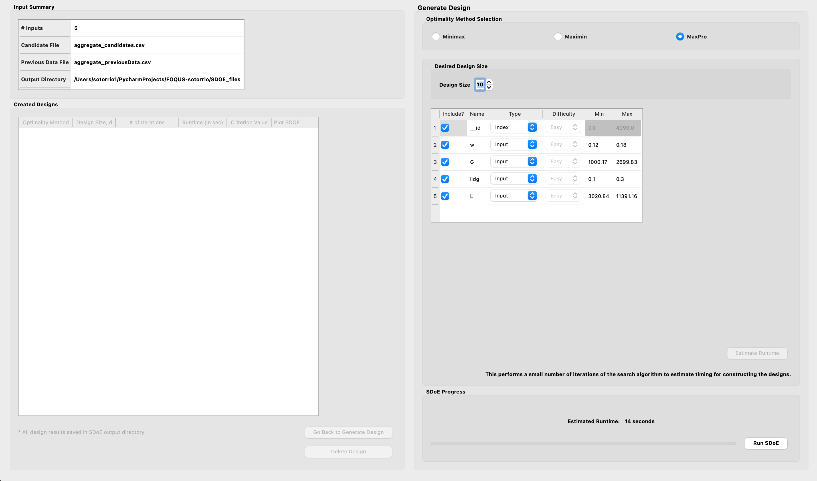
MaxPro Example 2: Design Setup
Select MaxPro for the type of design to create.
5. Select the Design Size to match what is desired. Recall that this will be the number of additional points that will be added to the existing design, not the total design size.
6. Next, select the options desired in the box: a) Should any of the columns be excluded from the design creation? If yes, then unclick the Include? box. b) For input factors to be used in the construction of the uniform space filling design, make sure that the Type is designated as Input. The automatically generated index column __id will be already listed as Index. c) Finally, you can optionally change the Min and Max ranges for the inputs to adjust the relative emphasis that distances in each input range are designated.
7. Once the set-up choices have been made, click Estimate Runtime to find out what the anticipated time is for generating the design.
8. After the SDoE module has created the design(s), the left window Created Designs is populated with the new design.
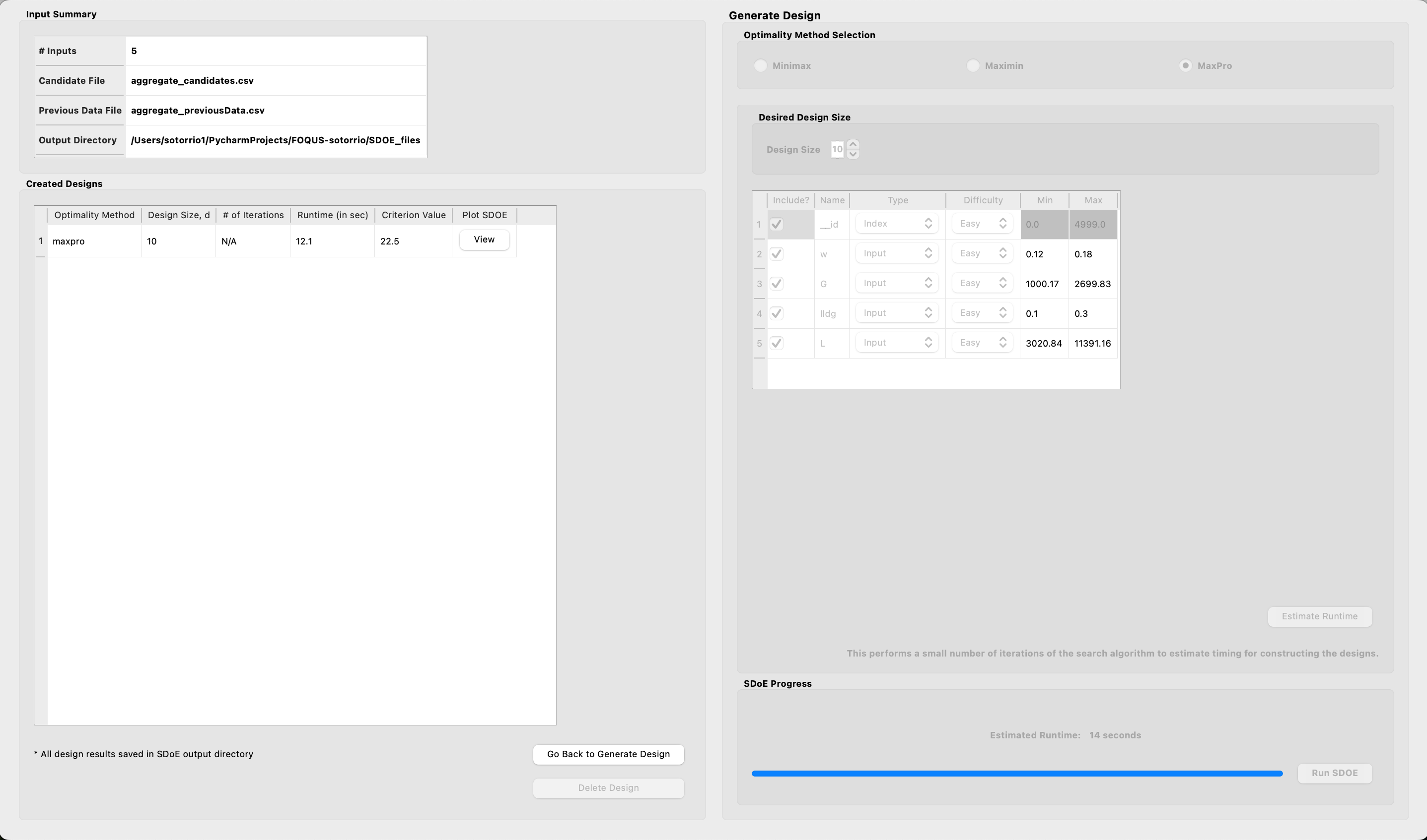
MaxPro Example 2: Created Design
9. You can visualize the design with the View option, where the plot now shows the Previous Data in pink, and the newly added possible design in blue. This allows better assessment of the appropriateness of the new design subject to the data that have already been collected.
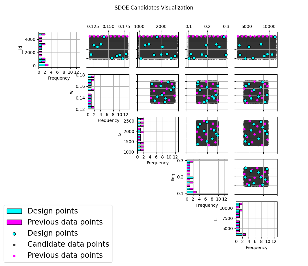
MaxPro Example 2: Plot Design